Recently I assembled an oxygen analyzer. The purpose of this device is to measure the oxygen content of a gas; for my purposes I’m using it to analyze breathing gases for diving.
Commercial analyzers are available at reasonable life-support prices. Having an interest in electronics hardware, I opted to use a DIY kit instead. For the search engines, that’s the “El Cheapo II oxygen analyzer” by OxyCheq. The kit is all the components to build an analyzer and a paper printout of instructions on how to put them together. I found the printout charming. Unfortunately I left it at the hardware store when I went there to get some snips and solder. This was a significant setback for me as this was my first electronics project of any sort and I had no idea what the hell I was doing. There’s no digital copy available for public download and obtaining one from the gentleman who owns & operates OxyCheq took some patience, but eventually I was able to get a replacement for the instructions and begin work on the analyzer.
Progress was slow. Building the unit involves cutting appropriate mounting holes into the generic black plastic case that comes in the kit. I found a Dremel ill suited to this task; the fiberglass cutting blades I had melted rather than cut the plastic. Nothing some filing couldn’t fix and eventually I had my holes cut.
After mounting all the stuff into the board I was ready for the electronics portion, which the instructions cheerily describe as the easy part. It turns out this is only true if you have a good soldering iron. The soldering iron I used at first was butane powered with a rather thick tip. With my unskilled, slow soldering operations, the butane kept running out. Part of building the kit involves removing a surface mount resistor. Doing this with a soldering tip that is as big as the entire surface mount component is difficult. Soldering components to the pads the SMT used to be on was, for my hand, nearly impossible. Almost immediately I ripped off one of the pads.
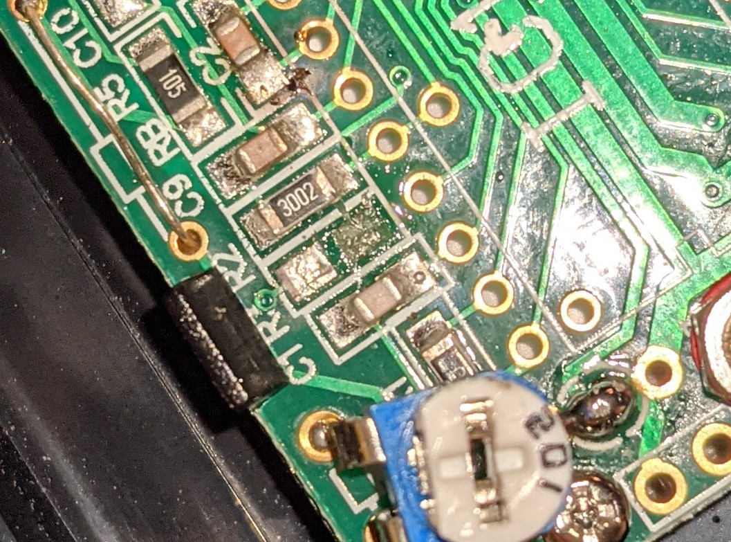
This was very disappointing. Being new to electronics I assumed I had destroyed the board and set about ordering a new one. I was able to find them here. There are several varieties of that board listed there with various possibly desirable features if you sort of know what you’re doing. I didn’t so I got the same model.
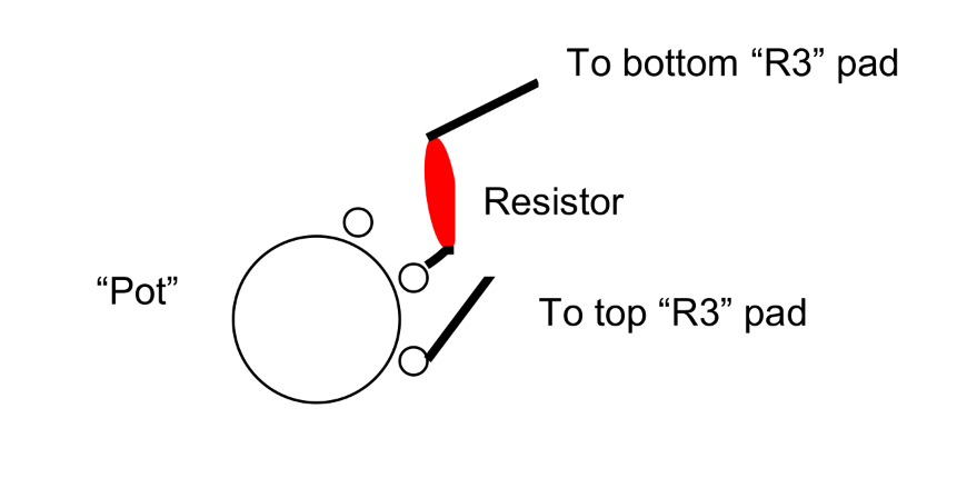
In the meantime some friends online who know things about electronics set me straight. They had a look at the board and noted that the bit of missing solder mask between the lower R3 and R2 pads, which suggested that they might be connected.
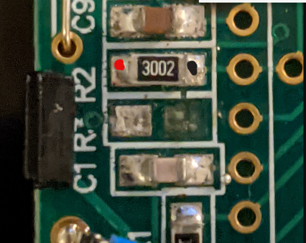
My friend made this helpful schematic.
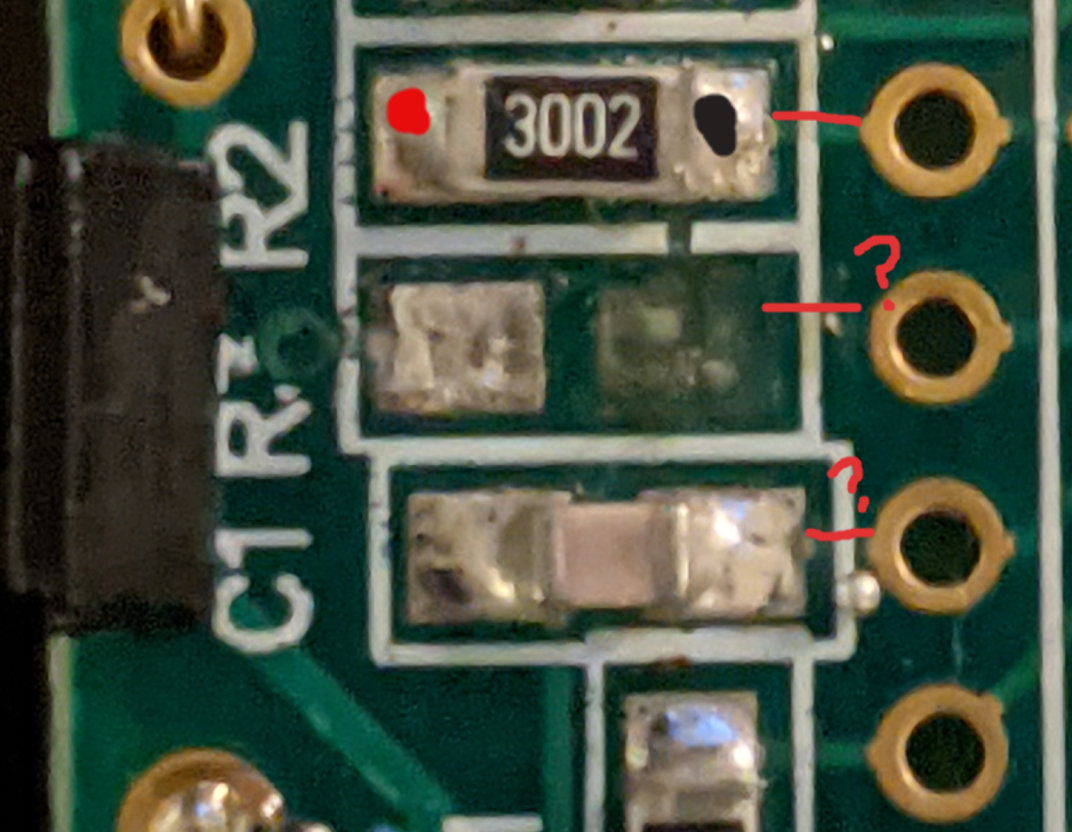
Unfortunately with no R2 pad I couldn’t verify this with an ohmeter, but I assumed that this was correct and proceeded to do a very bad solder joint to R3, which you can see in this picture along with some other similarly bad joints.
(Later, after completing the project, I found this thread which describes doing the exact same thing I did - and verifies that R2 and R3 pads are indeed connected. Oh well.)
After doing this joint and all the others, I plugged in the sensor, flipped on the meter, and to my dismay observed that the meter showed very negative, very positive or otherwise garbage values. Moreover it changed values if it was picked up.
By this time the other PM-128A I had ordered arrived, along with a much better soldering iron. Armed with proper tools and a fresh board I reworked all of the electronics. With the benefit of practice and my new iron the joints came out much better this time. Unfortunately the meter was as wrong as ever.
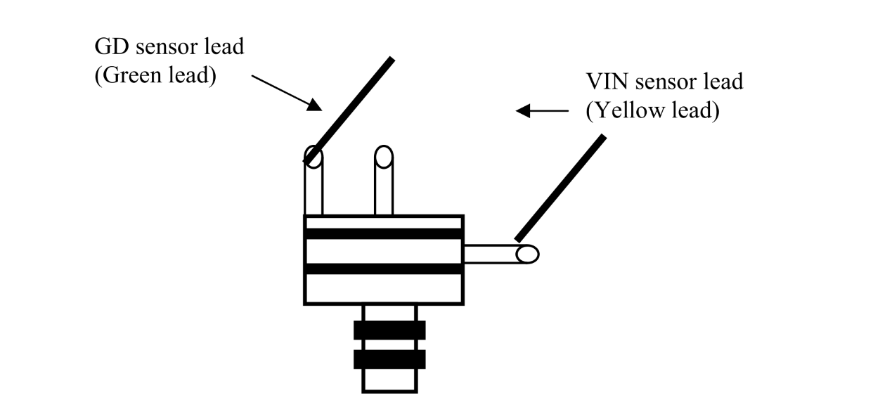
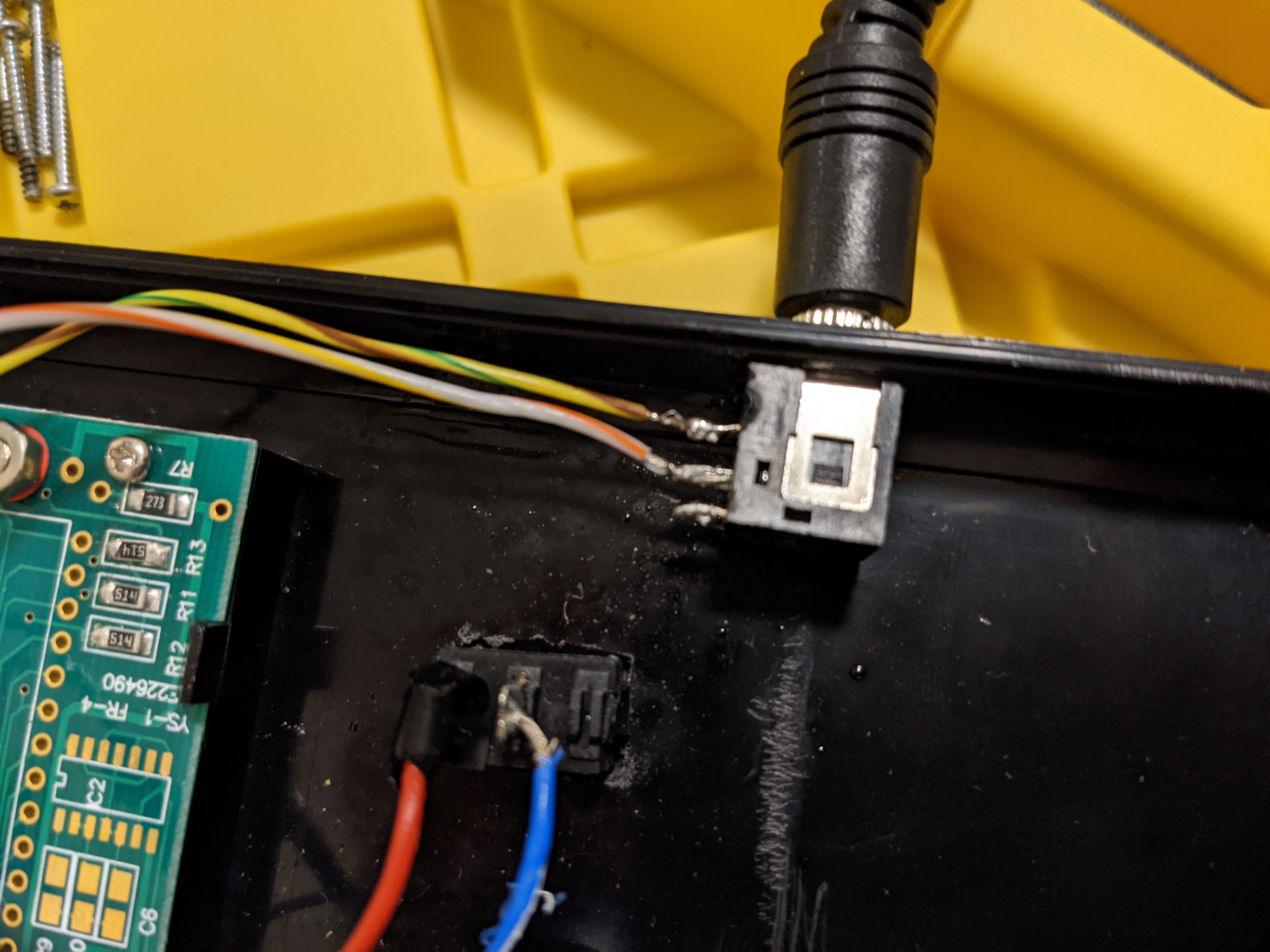
To cut a long story short, the oxygen sensor connects via a standard 3.5mm TRS jack. There are 3 pins on this jack. The jack part provided with the kit was different from the one described in the printout instructions. I had connected the voltmeter to the wrong pins on the jack, and one of the wrong pins was rather loose. Shaking this pin corresponded to the meter changes. I changed up the pins and the problem was solved.
Since I had trouble with some of the wiring instructions, I’m posting the correct wiring here in hopes someone else might find them useful.
Here’s the complete wiring diagram from the instructions:
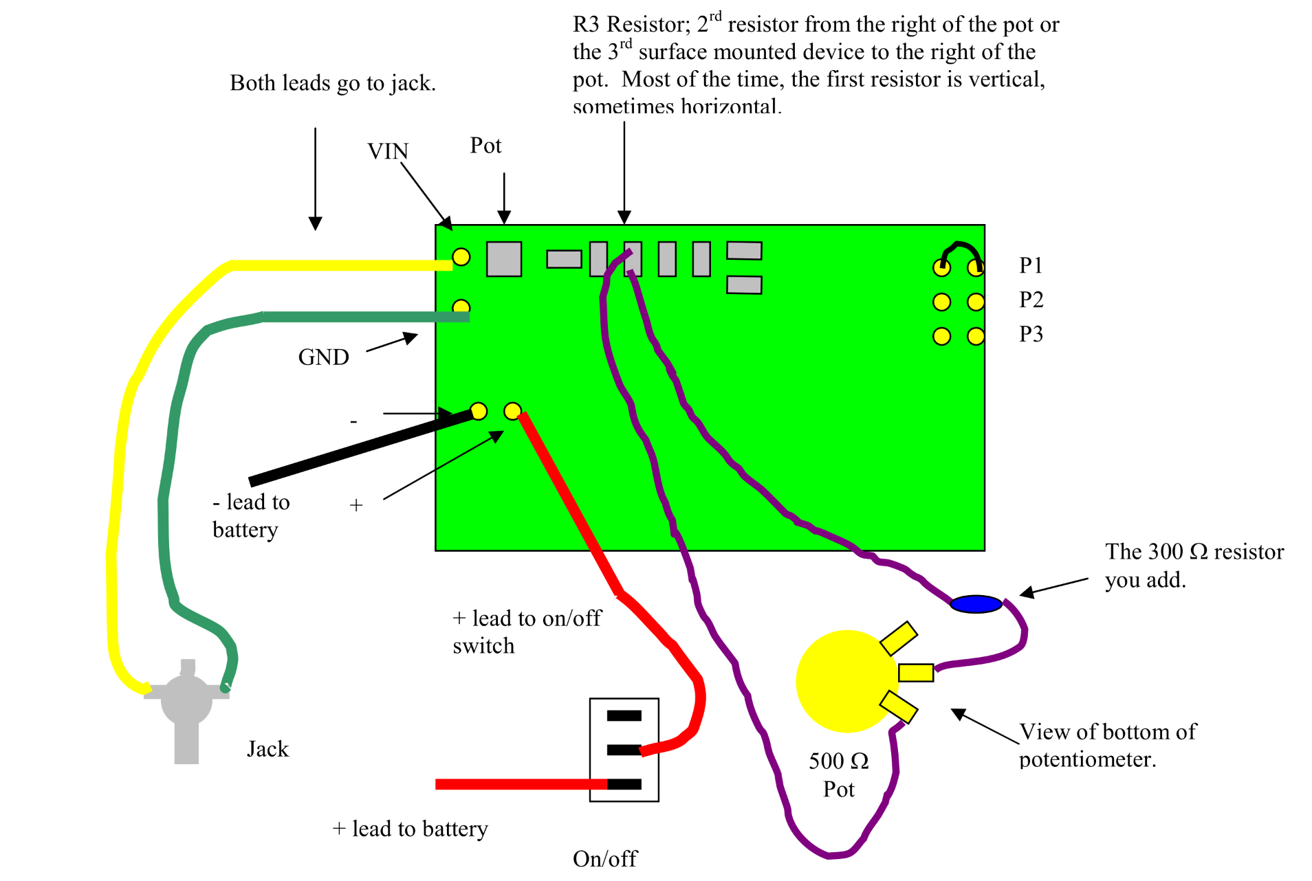
(See what I mean by charming? :-)
Jack wiring from the instructions:
Correct jack wiring (note wire colors):
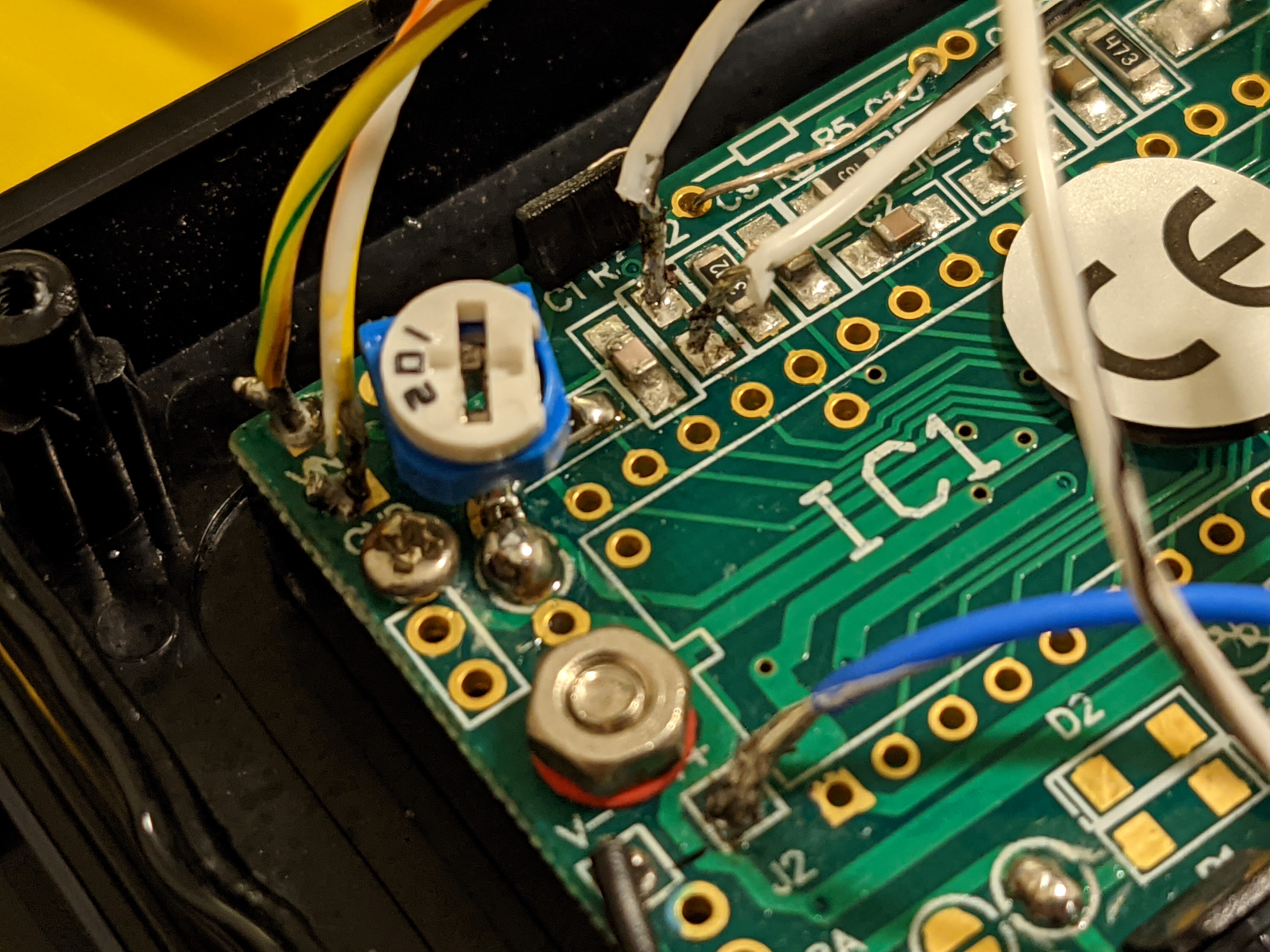
I also opted to use the upgraded 10 turn potentiometer, available from OxyCheq, rather than the standard one that comes with the kit. The difference is that it’s much more precise - the same range of values are covered in 10 turns of the knob versus 1, so it’s much easier to calibrate the meter down to a tenth of a percent. The downside is that the diagram in the instructions doesn’t cover this potentiometer, so some trial and error was required to find the appropriate wiring.
Pot wiring from the instructions:
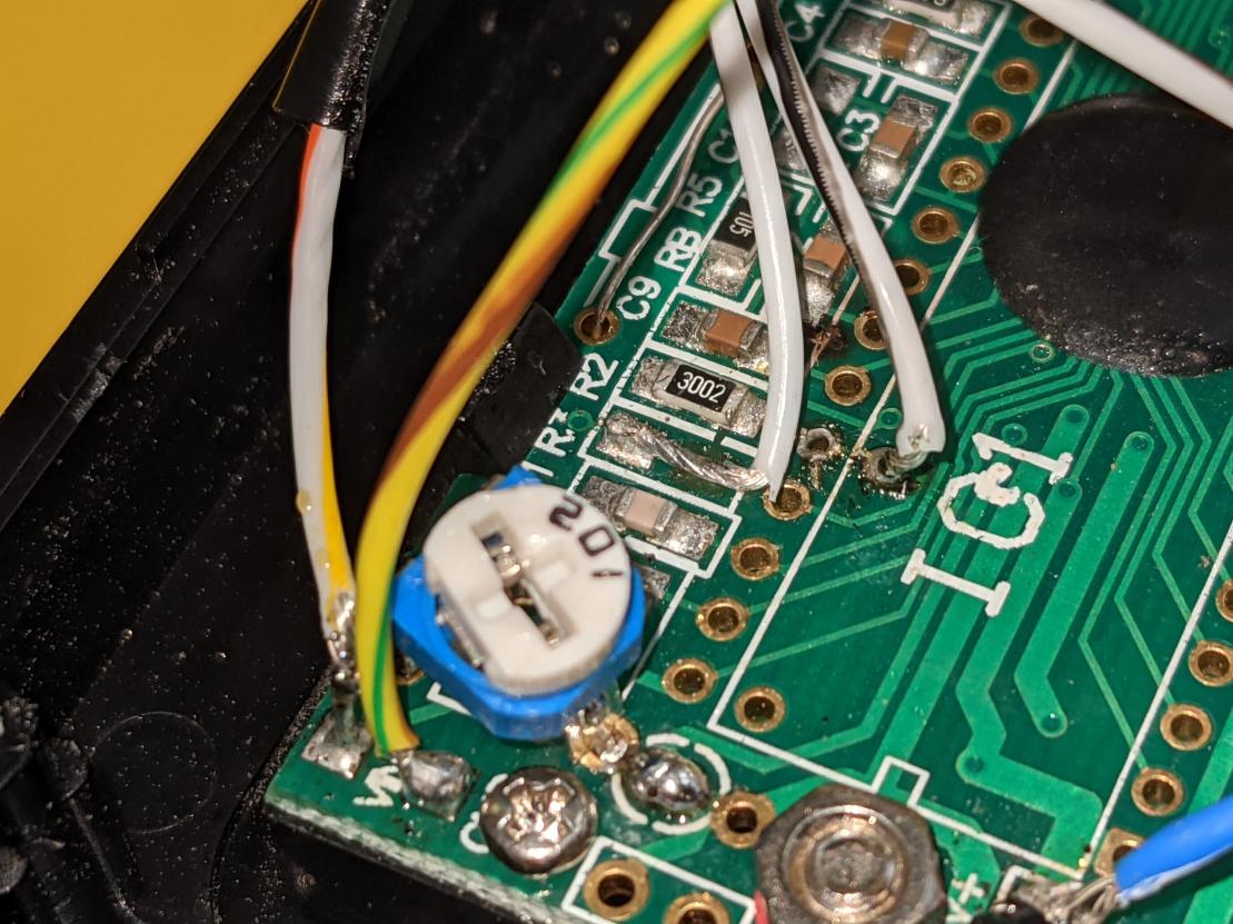
The correct pot wiring for the 10 turn pot is visible in this overall shot of the completed circuit.
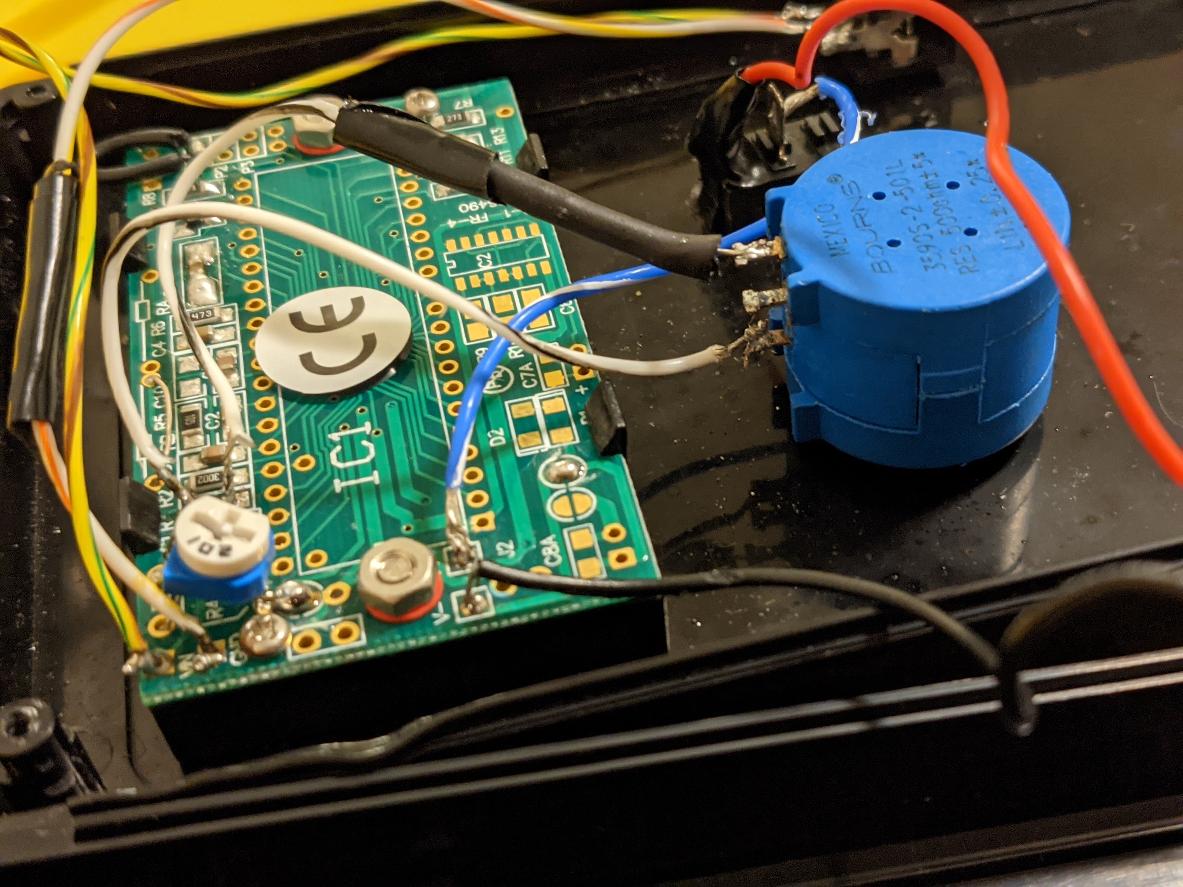
I know the joint on the lower leg of the pot looks horrible, I fixed it after that photo.
So does it work? Hell yeah! It really prefers being used on DIN valves with the DIN adapter available from OxyCheq, but I was able to get good test readings on EAN30 on a yoke valve with a bit of technique. I used it on a trip to the Spiegel Grove last week and it worked, although at the end of the trip the solder joint to the pot came loose, resulting in a constant reading of .03%. The important thing is that when it failed it failed in an obvious way.
The sensor used is a standard O2 sensor that you might find in a rebreather. Because it’s an off the shelf sensor, it can be easily replaced at the end of its service life, which is a significant advantage over some of the commercial analyzers.
I learned a lot from this project. In no particular order:
- Butane soldering irons and large tips are not ideal
- How to use an ohmeter and its applications
- Various types of solder and the utility of flux
- Much can be learned from solder mask
Thanks to the friends that helped me through my first electronics project!